Key Specs
| Spec | Value | Condition | Source |
|---|---|---|---|
| Function | Step-Down | [Digi-Key] | |
| Output Configuration | Positive | [Digi-Key] | |
| Topology | Buck | [Digi-Key] | |
| Output Type | Fixed | [Digi-Key] | |
| Number Of Outputs | 1 | [Digi-Key] | |
| Input Voltage (Min) | - | [Digi-Key] | |
| Input Voltage (Max) | 40V | [Digi-Key] | |
| Output Voltage (Min) | 12V | [Digi-Key] | |
| Output Voltage (Max) | - | [Digi-Key] | |
| Output Current (Max) | 3A | [Digi-Key] | |
| Switching Frequency (Typ) | 150kHz | [Digi-Key] | |
| Synchronous Rectifier | No | [Digi-Key] | |
| Operating Temperature Range | -40°C ~ 125°C (TJ) | [Digi-Key] | |
| Mounting Type | Through Hole | [Digi-Key] | |
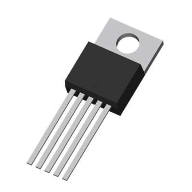
| Package Case | TO-220-5 | [Digi-Key] | |
| Supplier Device Package | TO-220-5L | [Digi-Key] |
When To Use
-
24V industrial supply → 12V @ 3A: The 40V input maximum comfortably covers a 24V nominal input with transient margin, while the 3A output current rating matches the load without risk of current limit triggering. Using a linear regulator here would cause excessive power dissipation, leading to thermal shutdown or severe derating.
-
Battery-powered system with 15V max input → 12V fixed output @ 3A: The fixed 12V output with ±4% overshoot tolerance simplifies design, and the 150kHz switching frequency balances efficiency and EMI. A synchronous buck controller would improve efficiency but add complexity and cost; a non-synchronous design like this avoids shoot-through faults common in synchronous stages.
-
Embedded system power rail from 30V supply → 12V @ 2.5A: The TO-220 package and thermal specs support moderate power dissipation at 3A max, suitable for this load. Using a high-frequency buck controller here could cause layout challenges with EMI due to much higher switching frequencies, while the chosen frequency and package ensure predictable thermal behavior.
When Not To Use
-
Output current demand > 3A continuous: The 3A max output current rating is a hard limit; pushing beyond risks current limit trips and thermal runaway. Use a multi-phase buck controller or high-current synchronous buck with external FETs instead for higher current capability and better thermal distribution.
-
Battery-powered device requiring ultra-low standby current: The typical quiescent current is 5mA, too high for μA-range sleep modes. Use a low-IQ PFM buck designed for sub-mA or μA quiescent current to maximize battery life.
-
Input voltage near output voltage (<1V differential) with noise-sensitive analog circuits: The minimum dropout voltage (~1.5V saturation voltage) and fixed switching frequency induce ripple and noise unacceptable in sensitive loads. Use an LDO regulator for clean, low-noise output with minimal dropout.
Application Notes
In the LM2596T-12 buck converter, the switching node (the junction between the internal switch and the external inductor) is the primary high-frequency switching point. This node requires the smallest possible PCB loop area to minimize EMI and voltage spikes. Keep the input capacitor, inductor, and diode physically close to this node to reduce parasitic inductances.
The feedback pin is noise-sensitive and must be routed carefully, away from the noisy switching node and any high-current traces. Use a low-impedance ground reference and shield the feedback trace to prevent voltage ripple from causing output voltage errors.
Thermal considerations are important: at the maximum output current of 3A and input voltages approaching 40V, the LM2596T-12 dissipates significant power. Given the TO-220-5 package thermal resistance junction-to-ambient of approximately 65°C/W, a suitable heatsink is recommended to maintain junction temperature below the maximum 125°C TJ rating, especially in ambient temperatures above 25°C.
Ensure the input voltage stays above the minimum recommended 15V and below the maximum 40V to maintain stable regulation. The internal oscillator frequency is typically 150kHz; layout and component selection should consider this switching frequency to optimize efficiency and minimize noise.
Finally, proper selection of external components as outlined in the BOM section is critical to prevent instability, excessive ripple, or thermal failure.
Minimum External Components
Catch diode — Schottky, Vr ≥ 40V, If ≥ 3A Selection: Schottky forward recovery < 10ns vs 200–500ns for silicon. At 150kHz (period = 6.7µs), a 500ns-recovery diode is off for only 6.2µs before the next switch-on — it never fully turns off. Failure mode: Standard silicon rectifier: 200–500ns reverse recovery at 150kHz causes shoot-through current spikes every cycle — IC switch current exceeds rating, causing thermal runaway or immediate failure.
Output inductor — 33µH Selection: Isat ≥ 3.8A (peak current at max load). DCR < 100mΩ to limit conduction loss. At Vin=20V→Vout=17.0V: range is 22–33µH (30%→15% current ripple). Use 33µH for good regulation; 22µH acceptable if BOM cost is critical. Isat must be ≥ 3.8A — under-sizing Isat is the leading cause of field failures: the inductor saturates under peak current, spiking IC switch current beyond its rating. Failure mode: Isat below peak inductor current → core saturates → effective inductance collapses → switch current spikes beyond IC rating → thermal shutdown or permanent failure.
Input capacitor — ≥100µF electrolytic + 100nF ceramic (parallel) Selection: Electrolytic handles bulk ripple current; ceramic bypasses switching spikes. Voltage rating ≥ 40V with 20% margin. Failure mode: Insufficient input capacitance: supply rail collapses during switch-on current demand → output droops → erratic regulation and potential latch-up.
Output capacitor — ≥100µF electrolytic Selection: ESR < 200mΩ to keep output ripple below 50mVpp. Voltage rating ≥ 30V. Failure mode: High-ESR electrolytic: output ripple voltage = ESR × ΔIL. At 1A ripple and 500mΩ ESR → 500mVpp ripple — exceeds spec for virtually all loads.
Design Equations
Inductor sizing: At Vin=20V→Vout=17.0V: range is 22–33µH (30%→15% current ripple). Use 33µH for good regulation; 22µH acceptable if BOM cost is critical. Isat must be ≥ 3.8A — under-sizing Isat is the leading cause of field failures: the inductor saturates under peak current, spiking IC switch current beyond its rating.
Gotchas
-
[Incorrect assumption about dropout voltage]: Designers may assume the saturation voltage of ~1.5V is constant over load and temperature. In reality, saturation voltage increases with load current and junction temperature, causing output voltage droop and instability near maximum load.
Fix: Measure saturation voltage under worst-case load and temperature conditions, and design input voltage headroom accordingly. -
[Minimum load required for stable regulation]: The LM2596T-12 can become unstable or oscillate if the output load is too light (<100mA typical). This results in output voltage ripple and possible audible noise.
Fix: Add a minimum load resistor or ensure load conditions never fall below device minimum to maintain stable operation. -
[Output capacitor ESR sensitivity]: Using ultra-low ESR ceramic capacitors alone on output can cause high-frequency ringing and output voltage spikes due to lack of internal damping.
Fix: Include a small ESR polymer or tantalum capacitor in parallel or select ceramic capacitors with appropriate ESR characteristics to maintain loop stability. -
[On/Off pin noise susceptibility]: The On/Off pin input current is small but can pick up noise if left floating or routed near the switching node, causing unintended shutdown or erratic switching behavior.
Fix: Tie the On/Off pin to a clean logic level via a resistor and avoid routing traces close to SW or noisy nodes.