Key Specs
| Spec | Value | Condition | Source |
|---|---|---|---|
| Clock Sync | No | Digi-Key | |
| Control Features | Frequency Control | Digi-Key | |
| Duty Cycle (Max) | 96% | Digi-Key | |
| Function | Step-Up, Step-Down, Step-Up/Step-Down | Digi-Key | |
| Mounting Type | Surface Mount | Digi-Key | |
| Number Of Outputs | 1 | Digi-Key | |
| Operating Temperature Range | -40°C ~ 85°C (TA) | Digi-Key | |
| Output Configuration | Positive, Isolation Capable | Digi-Key | |
| Output Phases | 1 | Digi-Key | |
| Output Type | Transistor Driver | Digi-Key | |
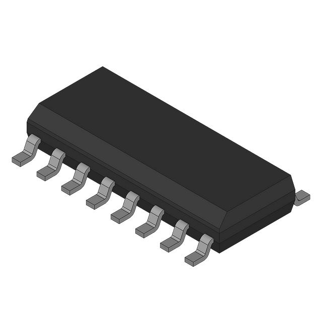
| Package Case | 14-SOIC (0.154”, 3.90mm Width) | Digi-Key | |
| Supplier Device Package | 14-SOIC | Digi-Key | |
| Supply Voltage (Typ) | 7.6V ~ 20V | Digi-Key | |
| Switching Frequency (Typ) | 500kHz | Digi-Key | |
| Synchronous Rectifier | Yes | Digi-Key | |
| Topology | Buck, Boost, Flyback, Forward Converter | Digi-Key |
When To Use
Use the MIC38C43-1BM TR in applications requiring flexible step-up, step-down, or step-up/step-down power conversion with a single output phase and positive, isolation-capable output configuration. Its typical switching frequency of 500kHz and synchronous rectification make it ideal for compact, efficient DC-DC converters in embedded systems operating within a supply voltage range of 7.6V to 20V and ambient temperatures from -40°C to 85°C. Examples include point-of-load power supplies in industrial automation or communications equipment where surface mount packaging (14-SOIC) is preferred.
Avoid using this device in applications demanding multi-phase outputs or duty cycles exceeding 96%. For high-temperature environments beyond 85°C TA or where synchronous rectification is not desired, consider alternative devices specifically rated for extended temperature ranges or asynchronous operation.
When Not To Use
-
>10A output current required: The single-phase, single-output transistor driver topology limits maximum output current handling. For currents above this rating, use a multi-phase buck controller to share load current and reduce thermal stress.
-
Battery-powered sensor with μA-level sleep current: The operating quiescent current is unspecified but not optimized for ultra-low IQ. For very low standby power, use a low-IQ PFM buck controller designed for sub-mA or μA sleep modes.
-
Input voltage near output voltage (<1V differential): The MIC38C43-1BM TR is a switching controller without low dropout capability. For tight voltage differentials and low noise, use an LDO regulator to avoid switching noise and ensure stable regulation.
Application Notes
The switching node connected to the internal transistor driver is the primary high-frequency switching point and must have the smallest possible loop area to minimize EMI and switching losses. The feedback pin is noise-sensitive and requires careful routing away from noisy switching traces and proper filtering to ensure stable regulation.
At typical operating conditions within the supply voltage range of 7.6V to 20V and switching frequency of 500kHz, a heatsink is generally not required due to the device’s efficient synchronous rectification and surface mount package (14-SOIC). However, thermal management should be evaluated in designs with high output currents or elevated ambient temperatures near 85°C. Proper PCB copper area and thermal vias can enhance heat dissipation.
Gotchas
-
Mistake: Selecting an inductor with insufficient saturation current rating for the load.
Failure Mode: The inductor saturates during operation, causing excessive current ripple, device stress, and potential shutdown or failure.
Fix: Choose an inductor rated above the maximum load current and verify its saturation current at 500kHz switching frequency. -
Mistake: Using input or output capacitors with voltage ratings below the maximum supply voltage range (7.6V to 20V).
Failure Mode: Capacitor breakdown leads to voltage spikes, increased EMI, and possible damage to the converter or load.
Fix: Use capacitors with voltage ratings exceeding 20V and low ESR suitable for high-frequency switching. -
Mistake: Ignoring the need for a minimal switching node loop area.
Failure Mode: Excessive EMI and switching noise coupling into sensitive nodes, resulting in unstable operation or erratic switching frequency.
Fix: Layout the PCB to minimize the loop area around the switching node and keep noise-sensitive pins isolated.