Key Specs
| Spec | Value | Condition | Source |
|---|---|---|---|
| Battery Chemistry | Lithium Ion/Polymer | Digi-Key | |
| Fault Protection | Over Current, Short Circuit | Digi-Key | |
| Function | Fuel Gauge | Digi-Key | |
| Grade | - | Digi-Key | |
| Interface | I2C, UART | Digi-Key | |
| Mounting Type | Surface Mount | Digi-Key | |
| Number Of Cells | 2 ~ 4 | Digi-Key | |
| Operating Temperature Range | -40°C ~ 85°C (TA) | Digi-Key | |
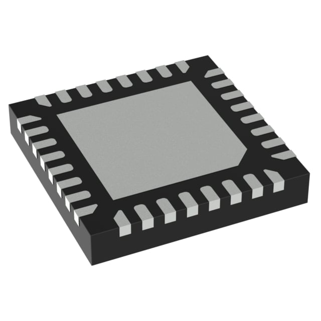
| Package Case | 32-VFQFN Exposed Pad | Digi-Key | |
| Qualification | - | Digi-Key | |
| Supplier Device Package | 32-HVQFN (4x4) | Digi-Key |
When To Use
-
2S–4S Li-Ion/Polymer battery fuel gauge: The RAJ240057A20DNP#HC1 supports 2 to 4 series cells and integrates over-current and short-circuit fault protection, making it ideal for monitoring pack state-of-charge with safety margin. Using a generic fuel gauge without integrated fault protection risks catastrophic thermal runaway if a short occurs undetected.
-
Battery management with I2C/UART comms in automotive or industrial environments: Its -40°C to 85°C operating range covers harsh ambient conditions typical in these sectors, while I2C and UART interfaces allow flexible system integration. Controllers limited to commercial temperature ranges or lacking robust fault detection can suffer latch-up or incorrect SOC reporting under temperature extremes.
-
Surface-mount, compact 32-VFQFN package for space-constrained designs: The exposed pad and 4x4 mm footprint ensure efficient thermal dissipation and PCB real estate savings. Using larger or through-hole alternatives risks poor thermal coupling, which can lead to thermal shutdown or premature aging in high-cycle battery systems.
When Not To Use
-
Output current > device rating or high transient load (> few amps): The RAJ240057A20DNP#HC1’s current handling is limited by its integrated protection and package constraints. For loads exceeding this, choose a high-current synchronous buck with external FETs to manage current and maintain efficiency under heavy load.
-
Applications needing switching frequencies above 500 kHz: This part’s design and package favor moderate-frequency operation. Use a high-frequency buck controller instead to reduce inductor size and EMI for frequencies beyond 500 kHz.
-
Low-power, coin-cell powered sensor nodes requiring ultra-low quiescent current: The RAJ240057A20DNP#HC1 does not specify µA-range standby current, so it will unnecessarily drain small batteries. A low-IQ PFM buck is better suited to minimize quiescent current and extend battery life in these scenarios.
Application Notes
-
The switching node (SW) pin requires a carefully controlled PCB layout with minimal loop area to reduce EMI and switching noise coupling into adjacent signal lines, especially near the I2C and UART pins.
-
Pins 3 and the I2C SDA/SCL or UART RX/TX pin are highly noise-sensitive; route these signals away from high di/dt nodes and provide local filtering or series resistors to prevent communication errors.
-
The exposed pad must be soldered directly to a large thermal PCB copper area connected to multiple vias for effective heat dissipation during continuous operation.
-
Guard routing or ground pours around the SW node and fault detection pins help suppress switching noise that could cause false fault triggers or misreporting in the fuel gauge.
-
Decoupling capacitors should be placed as close as possible to the supply pins to stabilize internal analog references and prevent ripple-induced measurement errors.
Gotchas
-
[Fault protection derating at low temperature]: The datasheet’s absolute maximum ratings do not explicitly show fault protection performance variation at -40°C. At cold extremes, internal threshold voltages can shift, causing delayed or missed over-current trips. Symptom: intermittent over-current events without fault indication, risking cell damage. Fix: Validate fault response across the full temperature range in system tests and apply conservative current limits at cold.
-
[Output capacitor ESR affects fuel gauge accuracy]: Using low-ESR ceramic capacitors alone can cause stability issues with internal measurement amplifiers, leading to SOC readout jitter or drift. Symptom: fluctuating SOC values during steady load conditions visible on the host interface. Fix: Add a small bulk tantalum or polymer capacitor with moderate ESR in parallel to smooth output and stabilize measurements.
-
[SW node layout coupling causes UART errors]: High di/dt switching currents on the SW node can induce voltage spikes on nearby UART RX/TX traces if routed too close or over the same ground return path. Symptom: corrupted data frames or communication hangs during load transients. Fix: Increase physical separation and use dedicated ground return for communication lines with guard traces.
-
[Startup sequencing with no load]: The fuel gauge can fail to initialize correctly if the battery load is zero or very light at power-up, causing the internal state machine to stall or lock in an incorrect state. Symptom: device appears dead or reports zero capacity despite a healthy battery. Fix: Ensure a minimum load during startup (e.g., small resistor or active load) to guarantee proper initialization.