Key Specs
| Spec | Value | Condition | Source |
|---|---|---|---|
| Function | Step-Up, Step-Up/Step-Down | Digi-Key | |
| Input Voltage (Max) | 40V | Digi-Key | |
| Input Voltage (Min) | 3.5V | Digi-Key | |
| Mounting Type | Through Hole | Digi-Key | |
| Number Of Outputs | 1 | Digi-Key | |
| Operating Temperature Range | -40°C ~ 125°C (TJ) | Digi-Key | |
| Output Configuration | Positive or Negative | Digi-Key | |
| Output Current (Max) | 3A (Switch) | Digi-Key | |
| Output Type | Adjustable | Digi-Key | |
| Output Voltage (Max) | 60V (Switch) | Digi-Key | |
| Output Voltage (Min) | 1.23V | Digi-Key | |
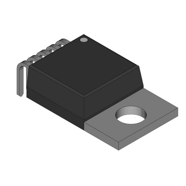
| Package Case | TO-220-5 Formed Leads | Digi-Key | |
| Supplier Device Package | TO-220-5 | Digi-Key | |
| Switching Frequency (Typ) | 52kHz | Digi-Key | |
| Synchronous Rectifier | No | Digi-Key | |
| Topology | Boost, Flyback, Forward Converter | Digi-Key |
When To Use
Use the LM2577T-ADJ/LB03 in applications requiring a single output boost or buck-boost (step-up/step-down) DC-DC converter with input voltages ranging from 3.5V to 40V and output voltages up to 60V. Typical applications include automotive power supplies where input voltage varies widely but output voltage regulation and up to 3A current capability are needed.
Do not use this device for applications requiring synchronous rectification or switching frequencies significantly higher than 52 kHz, as it lacks synchronous rectifier support and is optimized for 52 kHz operation. For low-voltage, high-efficiency applications requiring synchronous rectification or higher switching frequencies, consider other devices designed with those features.
When Not To Use
-
High-current 5V rail @ 10A: The 3A maximum switch current rating is insufficient for this load. Use a multi-phase buck controller instead to share current across phases and handle the higher load without device overstress.
-
Battery-powered sensor with μA sleep modes: The quiescent current is not optimized for ultra-low power standby operation. A low-IQ PFM buck regulator is needed to minimize battery drain during long sleep periods.
-
Input voltage above 40V or requiring galvanic isolation: The 40V maximum input rating limits use in higher-voltage or isolated systems. An isolated flyback converter should be selected to provide galvanic isolation and handle higher input voltages safely.
Application Notes
The LM2577T-ADJ/LB03’s switch pin is the primary switching node and must have the smallest possible loop area with the input inductor and diode to minimize EMI and switching losses. The feedback pin is noise-sensitive and should be routed away from the switch node and any high-current traces to ensure accurate voltage regulation.
At typical operating conditions near maximum load (3A switch current) and input voltage up to 40V, a suitable heatsink is recommended on the TO-220-5 package to maintain junction temperature within the -40°C to 125°C operating range. Thermal management is critical to prevent thermal shutdown and ensure long-term reliability.
Design Equations
Output voltage: Vout = 1.23V × (1 + R2/R1)
R1 is typically 1.21kΩ–10kΩ (1% tolerance). Solve for R2: R2 = R1 × (Vout/1.23 - 1). Example: for 5V with R1=1.21kΩ → R2 ≈ 3.74kΩ (use 3.74kΩ 1%).
Gotchas
-
Incorrect Inductor Current Rating:
Engineer selects an inductor rated below 3A.
Result: The inductor saturates under load, causing excessive ripple current, device overheating, and possible shutdown or failure.
Fix: Use an inductor rated for at least 3A continuous current to prevent saturation and maintain stable operation. -
Insufficient Diode Voltage Rating:
Engineer uses a diode rated below the 60V maximum output voltage.
Result: The diode can break down during voltage spikes, causing device damage and circuit failure.
Fix: Select a diode with a reverse voltage rating comfortably above 60V, such as 70V or higher, to ensure reliability. -
Large Feedback Loop Area:
Engineer routes feedback and switch node traces with large loop areas.
Result: Increased electromagnetic interference (EMI) and unstable output voltage regulation.
Fix: Keep the feedback loop area as small as possible by placing feedback resistors close to the device and minimizing trace lengths.