Key Specs
| Spec | Value | Condition | Source |
|---|---|---|---|
| Control Features | - | Digi-Key | |
| Current Quiescent IQ | 4 µA | Digi-Key | |
| Input Voltage (Max) | 6V | Digi-Key | |
| Mounting Type | Surface Mount | Digi-Key | |
| Number Of Regulators | 1 | Digi-Key | |
| Operating Temperature Range | -40°C ~ 125°C | Digi-Key | |
| Output Configuration | Positive | Digi-Key | |
| Output Current (Max) | 250mA | Digi-Key | |
| Output Type | Fixed | Digi-Key | |
| Output Voltage (Max) | - | Digi-Key | |
| Output Voltage (Min) | 3.3V | Digi-Key | |
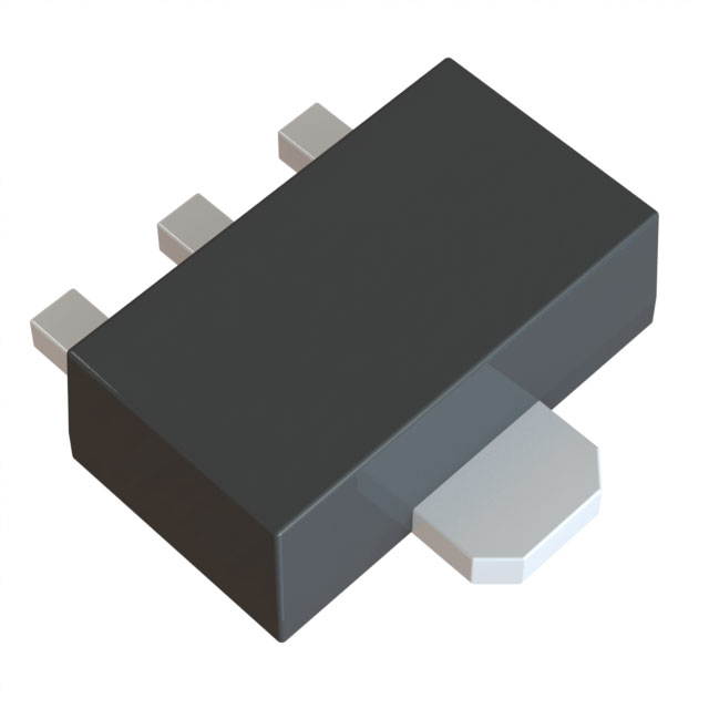
| Package Case | TO-243AA | Digi-Key | |
| Protection Features | Over Current, Over Temperature, Short Circuit | Digi-Key | |
| Psrr | 44dB (100Hz) | Digi-Key | |
| Supplier Device Package | SOT-89-3 | Digi-Key | |
| Voltage Dropout (Max) | 0.35V @ 250mA | Digi-Key |
When To Use
-
3.3V @ 250mA from a 6V input rail: The 6V maximum input voltage and 250mA output current rating align perfectly with this regulator’s capability, ensuring safe operation without thermal shutdown. Switching regulators or synchronous buck controllers would be more complex and risk shoot-through losses at these low currents, while this LDO provides simplicity and stable fixed output.
-
Battery-powered sensor node requiring ultra-low quiescent current: With a quiescent current of just 4 µA, this device minimizes battery drain during standby, extending operational life. A switching regulator might reduce load losses but would consume significantly higher quiescent current, causing premature battery depletion.
-
3.3V output rail for sensitive analog circuits needing low noise: The 44dB PSRR at 100Hz and fixed output voltage ensure clean power delivery, reducing ripple-induced errors. Switching regulators often inject high-frequency noise and require additional filtering, risking analog performance degradation.
When Not To Use
-
Load currents above 250mA continuous: The 250mA max output current rating disqualifies this part; pushing beyond risks thermal runaway and device shutdown. Use a high-current synchronous buck with external FETs to safely handle higher currents with better efficiency.
-
Input voltages exceeding 6V or wide transient margins needed: The 6V max input voltage rating limits use on higher-voltage rails or those with load-dump spikes. Choose a synchronous buck controller designed for higher voltage tolerance and robust transient handling.
-
Applications with input-output voltage differential below 0.35V: The dropout voltage of 0.35V at full load is too high for tight headroom designs that require low dropout and low noise. Use an LDO regulator optimized for ultra-low dropout conditions in such cases.
Application Notes
The MCP1700T-3302E/MB features a fixed 3.3 V output with a maximum output current of 250 mA. The input voltage can be up to 6 V, with a maximum dropout voltage of 0.35 V at full load.
-
The input pin is the switching node where input voltage is regulated; it requires a small loop area with the input capacitor to minimize noise and ensure stable operation.
-
The output pin is noise-sensitive and must be decoupled with the recommended output capacitor placed as close as possible to the device to maintain stability and minimize output voltage ripple.
-
Due to the low quiescent current (4 µA) and low dropout voltage, the device is well suited for battery-powered applications.
-
The device package (TO-243AA / SOT-89-3) provides limited thermal dissipation; at maximum load (250 mA) and worst-case conditions, a heatsink is generally not required, but proper PCB thermal design is recommended to maintain junction temperature within the -40°C to 125°C operating range.
-
Protection features include Over Current, Over Temperature, and Short Circuit protection, which help safeguard the device in fault conditions but should not be relied upon as a substitute for proper design and layout.
Gotchas
-
[Thermal derating at elevated ambient temperatures]: The maximum output current rating of 250mA is only guaranteed at 25°C junction temperature. At higher ambient temperatures approaching 125°C, the device will enter thermal shutdown or reduce output current capability silently. Fix by verifying junction temperature with accurate thermal modeling and derating output current accordingly.
-
[Output capacitor ESR impact on stability]: Using a ceramic output capacitor with excessively low ESR can cause regulator instability or oscillations not predicted by simple datasheet curves. Fix by selecting a capacitor with ESR within recommended range or adding a small series resistor to dampen potential oscillations.
-
[Failure due to input voltage transients]: Applying input voltages close to or above 6V transiently (e.g., during power surges) can cause latch-up or permanent damage despite short-term compliance. Fix by adding adequate input transient suppression such as TVS diodes and verifying worst-case input conditions on the bench.
-
[Startup issues with minimum load]: The regulator may fail to start or exhibit output voltage drop if the load current is extremely low or nonexistent, due to internal bias current requirements. Fix by adding a minimum load resistor (~10kΩ) to ensure stable startup and regulation under all load conditions.