MCP14A0302T-E/KBA vs 1EDI20N12AFXUMA1 Gate Driver ICs: A Component Comparison
Quick verdict
For general-purpose gate driving of IGBTs or MOSFETs in cost-sensitive, low-voltage applications (4.5–18 V supply), the MCP14A0302T-E/KBA offers straightforward, high peak current drive with fast switching times and a compact WDFN footprint. Conversely, the 1EDI20N12AFXUMA1’s magnetic coupling isolation and higher voltage range (10–35 V) make it a better fit for isolated gate drive applications in industrial or automotive systems requiring galvanic isolation and higher junction temperature tolerance.
Spec comparison table
| Spec | MCP14A0302T-E/KBA | 1EDI20N12AFXUMA1 | Notes |
|---|---|---|---|
| Channel type | Single | Single | Equal, both single-channel drivers |
| Current peak output source/sink | 3 A / 3 A | Not specified | MCP14A0302T provides explicit 3 A peak drive, better for controlling large gate charge |
| Driven configuration | High-Side, Low-Side | Not specified | MCP14A0302T explicitly supports both, 1EDI20N12AFXUMA1 datasheet doesn’t specify |
| Gate type | IGBT | Not specified | MCP14A0302T targets IGBTs; Infineon part likely MOSFET-compatible but not explicitly stated |
| Input type | Non-Inverting | Not specified | MCP14A0302T is non-inverting; 1EDI20N12AFXUMA1 input polarity unknown |
| Logic voltage V_IL / V_IH | 0.8 V / 2 V | Not specified | MCP14A0302T is compatible with standard 3.3/5 V logic; Infineon input thresholds unknown |
| Mounting type | Surface Mount, Wettable Flank | Surface Mount | MCP14A0302T WDFN with wettable flanks eases visual inspection and soldering reliability |
| Number of drivers | 1 | 1 | Equivalent |
| Operating temperature range | -40°C to 125°C (TA) | -40°C to 150°C (TJ) | Infineon supports higher max junction temp, better for harsh thermal environments |
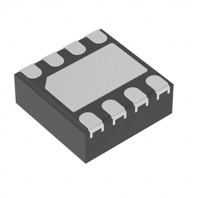
| Package case | 8-WDFN (2x2 mm) | 8-SOIC (3.9 mm width) | MCP14A0302T smaller footprint, better for high-density layouts |
| Rise/fall time (typical) | 13 ns / 12 ns | 10 ns / 9 ns | Infineon is slightly faster, beneficial for high-frequency switching |
| Supply voltage range | 4.5 V to 18 V | 10 V to 35 V | Infineon supports higher supply voltage, suitable for higher-voltage gate drive rails |
| Technology | Standard gate driver IC | Magnetic coupling isolation | Infineon provides galvanic isolation, critical for noise immunity and safety |
Design trade-offs
The MCP14A0302T-E/KBA is a conventional, non-isolated gate driver optimized for driving IGBTs and MOSFETs directly from logic-level inputs, with a peak source and sink current of 3 A. This level of drive current balances the need to charge/discharge gate capacitances quickly to minimize switching losses and EMI, without requiring complex layout or isolated power supplies. Its supply voltage range of 4.5 V to 18 V accommodates common gate drive voltages, including 12 V rails, and its compact 2x2 mm 8-WDFN package with wettable flanks improves manufacturability and thermal dissipation, making it suitable for dense power modules or compact DC-DC converters. The typical rise/fall times of around 12–13 ns support switching frequencies into the hundreds of kHz, assuming the MOSFET/IGBT gate charge is moderate.
In contrast, the Infineon 1EDI20N12AFXUMA1 uses magnetic coupling for galvanic isolation, allowing it to provide gate drive signals without a direct electrical connection. This is a significant design advantage when isolation barriers are mandatory, such as in industrial motor drives or automotive inverters, to prevent ground loops and improve system safety. Its operating voltage supply is higher (10 V to 35 V), enabling direct driving of high-voltage MOSFET or IGBT gates with robust margins, often required in 600 V-class power stages. The slightly faster typical rise/fall times (9–10 ns) reduce switching losses further but come at the cost of a larger SOIC package (3.9 mm wide) and more complex layout considerations to maintain isolation integrity.
Thermally, the MCP14A0302T-E/KBA is limited to 125°C ambient, while the Infineon device is rated to 150°C junction temperature, advantageous in high-temperature environments or where cooling is limited. The magnetic coupling technology generally introduces higher cost and layout complexity but can eliminate optocouplers or transformer driver circuits, simplifying overall system design.
From a firmware perspective, the MCP14A0302T-E/KBA’s defined logic thresholds (0.8 V low, 2 V high) provide predictable interfacing with common logic families, while the Infineon driver’s input characteristics are less transparent, potentially requiring characterization or reference to full datasheets.
Cost-wise, MCP14A0302T-E/KBA likely offers a lower per-unit price and PCB area, suitable for volume consumer or industrial applications without isolation requirements. The 1EDI20N12AFXUMA1 targets niche applications where isolation justifies higher BOM cost and PCB complexity.
Use-case fit
Choose MCP14A0302T-E/KBA when:
- Designing non-isolated gate drive circuits for IGBTs or MOSFETs operating from 5 V to 18 V gate drive rails.
- Space is at a premium, and a small 2x2 mm WDFN package simplifies high-density PCB layouts.
- You require a gate driver with explicit, balanced 3 A peak source and sink capability for moderate-speed switching.
- Logic input compatibility with 3.3 V or 5 V microcontrollers or DSPs is required without additional level shifting.
- Operating temperature rarely exceeds 125°C ambient and cost sensitivity is a priority.
Choose 1EDI20N12AFXUMA1 when:
- Galvanic isolation between control and power circuits is mandatory, such as in industrial motor drives or automotive inverter stages.
- The gate drive voltage needs to exceed 18 V, up to 35 V, to fully enhance high-voltage MOSFETs or IGBTs.
- The system operates in harsh environments where junction temperatures can reach 150°C.
- Slightly faster switching (rise/fall times ~9–10 ns) is needed to optimize efficiency in high-frequency switching applications.
- Larger PCB area and higher BOM cost are acceptable in exchange for isolation benefits.
Drop-in compatibility
These parts are not pin-compatible nor footprint-compatible. MCP14A0302T-E/KBA uses a compact 8-WDFN (2x2 mm) package with wettable flanks, while the 1EDI20N12AFXUMA1 is housed in an 8-pin SOIC (3.9 mm wide) package. Pin assignments, input/output configurations, and power supply connections differ significantly due to the differing technologies (non-isolated vs. magnetic coupling isolation). Substituting one for the other requires PCB redesign and potentially changes in gate drive power supplies and isolation schemes. The data provided does not specify pin mapping, so no direct swap is possible without a redesign.
Alternatives to consider
- UCC37322 (Texas Instruments): A dual high-speed MOSFET driver with up to 9 A peak current, suitable for high-frequency, high-current gate drive applications.
- IR2110 (Infineon): A popular high-side/low-side driver IC with level shifting and bootstrap support, widely used in half-bridge topologies.
- ADuM4223 (Analog Devices): A digital isolated gate driver using iCoupler technology, combining isolation with high transient immunity for industrial applications.