MAX17330X22+T vs MAX17301G+ Battery Fuel Gauge ICs: A Component Comparison
Quick verdict
For compact, space-constrained designs prioritizing minimal PCB footprint and package height, the MAX17330X22+T’s smaller 15-WLP (1.91x2.45 mm) package is the better choice. For applications where thermal dissipation and simpler PCB layout are more important, the MAX17301G+ with its larger 14-TDFN (3x3 mm) package and exposed pad offers an advantage. Both share near-identical functional specs, so the decision primarily hinges on mechanical and thermal considerations.
Spec comparison table
| Spec | MAX17330X22+T | MAX17301G+ | Notes |
|---|---|---|---|
| Battery chemistry | Lithium Ion/Polymer | Lithium Ion/Polymer | Identical chemistry support, no difference. |
| Fault protection | Over Current, Over Temperature, Over/Under Voltage, Short Circuit | Over Current, Over Temperature, Over/Under Voltage, Short Circuit | Equivalent fault protection features. |
| Function | Fuel Gauge | Fuel Gauge | Same core function. |
| Interface | I2C | I2C | Identical communication interface. |
| Mounting type | Surface Mount | Surface Mount | Both surface mount; no difference. |
| Number of cells | 1 | 1 | Same single-cell support. |
| Operating temperature range | -40°C to 85°C | -40°C to 85°C | Same operating range. |
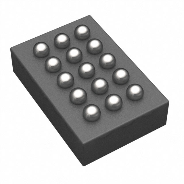
| Package case | 15-WFBGA, WLBGA (15-WLP, 1.91x2.45 mm) | 14-WFDFN Exposed Pad (14-TDFN, 3x3 mm) | MAX17330X22+T has smaller package footprint (beneficial for compact designs); MAX17301G+ larger with exposed pad improves thermal dissipation. |
| Supplier device package | 15-WLP (1.91x2.45) | 14-TDFN (3x3) | Smaller MAX17330X22+T package reduces PCB area; MAX17301G+’s exposed pad aids heat sinking. |
Design trade-offs
The most significant design difference lies in the package and associated thermal characteristics. The MAX17330X22+T uses a wafer-level package (WLP) measuring 1.91 x 2.45 mm, which drastically reduces PCB area and profile. This is ideal for ultra-compact devices like wearables or slim mobile products. However, WLPs typically have less effective thermal conduction paths compared to exposed-pad QFN packages, which can limit continuous current handling or require more careful thermal management in high-power scenarios.
Conversely, the MAX17301G+ comes in a 14-TDFN package with an exposed pad, measuring 3 x 3 mm. This larger package footprint facilitates improved thermal conduction to the PCB, enabling better heat dissipation. It also simplifies PCB layout for thermal vias and ground plane connections. From a manufacturing standpoint, exposed pad QFNs are generally easier to inspect and rework than WLPs, which can be an important consideration on production lines.
Both devices support the same fault protection features and communicate over I2C, so firmware integration differences are minimal. However, the MAX17301G+ may afford more stable thermal conditions, potentially reducing the need for aggressive thermal derating or complex calibration under heavy load.
Regarding cost, wafer-level packages tend to be more expensive per unit and require tighter assembly controls, but they reduce overall BOM cost by minimizing PCB size and materials. The MAX17301G+’s larger package might be cheaper and easier to assemble but increases PCB real estate and possibly the overall product thickness.
No efficiency or electrical performance curves are explicitly provided, but both devices support single-cell lithium chemistries and identical fault protections, so electrical performance can be assumed comparable. Layout sensitivity is higher for the WLP due to its smaller size and tighter pad pitches, which may require more precise PCB fabrication and assembly processes.
Use-case fit
Choose MAX17330X22+T when…
- You are designing a highly space-constrained wearable device or ultra-thin mobile product where PCB area and profile are critical.
- Your design requires a minimal BOM footprint and you have access to high-quality PCB fabrication and assembly processes to handle WLP packages reliably.
- Thermal dissipation requirements are moderate, and you can manage heat through system-level design or lower average currents.
- You want to minimize overall product thickness without sacrificing fuel gauge functionality.
- Your application involves a single-cell Li-ion/polymer battery and I2C interface, making the MAX17330X22+T a straightforward fit.
Choose MAX17301G+ when…
- Your design requires better thermal management for higher continuous current or operating in thermally challenging environments.
- You prefer a package with an exposed pad for easier thermal via implementation and improved heat conduction.
- PCB real estate is less constrained, and you prioritize easier inspection and rework on the assembly line.
- You want a proven QFN package form factor that is widely supported by standard PCB fabrication and assembly processes.
- Your product demands robust mechanical reliability and lower assembly risk, especially in mid-volume to high-volume manufacturing.
Drop-in compatibility
Based on the data, these two devices differ significantly in package type and size: MAX17330X22+T uses a 15-WLP (1.91x2.45 mm) package, while MAX17301G+ uses a larger 14-TDFN (3x3 mm) package with an exposed pad. There is no indication they share pinouts or footprint compatibility. Substituting one for the other would require a PCB redesign to accommodate different pad layouts and thermal management strategies. Firmware interface compatibility is assured via I2C, but hardware-level substitution is not drop-in.
Alternatives to consider
- MAX17043: Simplified fuel gauge with minimal external components for cost-sensitive designs.
- BQ27441 (Texas Instruments): Offers extensive configurability and proven gauge accuracy for single-cell Li-ion/polymer batteries.
- LTC2942 (Analog Devices/Linear Technology): Combines coulomb counting with voltage and temperature monitoring in a compact form factor.