Key Specs
| Spec | Value | Condition | Source |
|---|---|---|---|
| Control Features | Soft Start | Digi-Key | |
| Duty Cycle | 72% | Digi-Key | |
| Fault Protection | Current Limiting, Open Loop, Over Load, Over Temperature, Over Voltage | Digi-Key | |
| Internal Switch S | Yes | Digi-Key | |
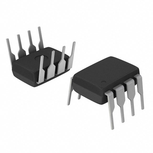
| Mounting Type | Through Hole | Digi-Key | |
| Operating Temperature Range | -25°C ~ 130°C (TJ) | Digi-Key | |
| Output Isolation | Isolated | Digi-Key | |
| Package Case | 8-DIP (0.300”, 7.62mm) | Digi-Key | |
| Power Watts | 68 W | Digi-Key | |
| Supplier Device Package | PG-DIP-8 | Digi-Key | |
| Supply Voltage (Typ) | 8.5V ~ 21V | Digi-Key | |
| Switching Frequency (Typ) | 67kHz | Digi-Key | |
| Topology | Flyback | Digi-Key | |
| Voltage Breakdown | 650V | Digi-Key | |
| Voltage Start Up | 15 V | Digi-Key |
When To Use
Use the ICE3B2565FKLA1 when designing isolated flyback converters requiring moderate power up to 68W, operating from supply voltages between 8.5V and 21V, and where integrated protections and an internal switch simplify design. Its 72% duty cycle and 67kHz switching frequency make it suitable for offline adapters and auxiliary power supplies with tight thermal constraints (-25°C to 130°C TJ rating).
Avoid using this device in high power applications exceeding 68W or where surface mount packages are mandatory; in such cases, consider Infineon’s higher power or SMD package devices. Also, for non-isolated buck or boost topologies, choose dedicated controllers designed for those topologies rather than this flyback-specific IC.
When Not To Use
-
Non-isolated 5V @ 10A point-of-load: The 68W max power and isolation requirement disqualify this part; use a high-current synchronous buck with external FETs for better efficiency and current capacity.
-
Battery-powered sensor with μA standby current: The internal switch and flyback topology mean quiescent current is too high for low-power sleep modes. Use a low-IQ PFM buck controller instead.
-
High-frequency DC-DC converter > 500kHz switching: The fixed 67kHz switching frequency limits transient response and size reduction; use a high-frequency buck controller for smaller magnetics and faster transient handling.
Application Notes
The internal switch connected to the drain pin switches at 67kHz and requires minimizing the loop area formed by the drain, input capacitor, and transformer primary to reduce EMI and switching losses. The feedback pin is noise-sensitive; routing it away from switching nodes and using proper filtering is essential for stable regulation. At the maximum rated power of 68W, a suitable heatsink or adequate PCB copper area is necessary to maintain the junction temperature below 130°C. The device’s integrated protections reduce external component count but do not replace good layout and thermal design practices.
Gotchas
-
Incorrect transformer design:
- Engineer uses a transformer not optimized for 67kHz switching frequency or flyback topology.
- Result: Increased EMI, poor regulation, and potential device overheating.
- Fix: Use a transformer designed specifically for 67kHz flyback operation matching input/output voltage and power ratings.
-
Ignoring thermal limits:
- Engineer omits adequate thermal management despite 130°C TJ max rating and 68W power dissipation.
- Result: Device overheats, triggering over temperature protection or causing premature failure.
- Fix: Provide proper heatsinking or PCB copper area to maintain junction temperature within limits during maximum load.
-
Supply voltage outside specified range:
- Engineer applies startup or operating voltage below 8.5V or above 21V.
- Result: Device may fail to start or suffer damage due to overvoltage.
- Fix: Ensure supply voltage stays within 8.5V to 21V during all operating conditions.