Key Specs
| Spec | Value | Condition | Source |
|---|---|---|---|
| Control Features | EN, Soft Start | Digi-Key | |
| Duty Cycle | 75% | Digi-Key | |
| Fault Protection | Over Load, Over Temperature, Over Voltage | Digi-Key | |
| Internal Switch S | Yes | Digi-Key | |
| Mounting Type | Through Hole | Digi-Key | |
| Operating Temperature Range | -25°C ~ 125°C (TJ) | Digi-Key | |
| Output Isolation | Isolated | Digi-Key | |
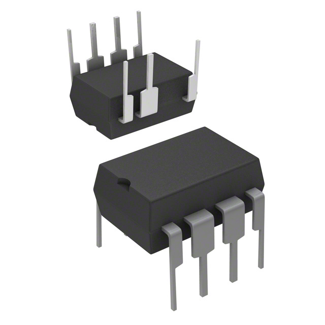
| Package Case | 8-DIP (0.300”, 7.62mm), 7 Leads | Digi-Key | |
| Power Watts | 43 W | Digi-Key | |
| Supplier Device Package | PG-DIP-7 | Digi-Key | |
| Supply Voltage (Typ) | 10.5V ~ 25V | Digi-Key | |
| Switching Frequency (Typ) | 100kHz | Digi-Key | |
| Topology | Flyback | Digi-Key | |
| Voltage Breakdown | 800V | Digi-Key | |
| Voltage Start Up | 17 V | Digi-Key |
When To Use
Use the ICE3AR2280JZ2XKLA1 in isolated flyback power supplies requiring up to 43 W output power, operating within a supply voltage range of 10.5 V to 25 V, and needing robust fault protection (overload, over temperature, over voltage). Typical applications include low-to-medium power adapters and auxiliary power supplies where through-hole mounting and 8-DIP package are preferred.
Do not use this device for high-frequency (>100 kHz) or high-power (>43 W) applications, as the switching frequency and power rating limit efficiency and thermal performance. For higher power or surface-mount requirements, consider Infineon’s higher power integrated controllers or modules with advanced packaging and higher switching frequencies.
When Not To Use
-
High-current output > 3A continuous: The 43W power rating and internal switch limit current capability for loads demanding more than ~3A continuous. Use a multi-phase buck controller instead to spread losses and avoid thermal overstress.
-
Battery-powered devices requiring ultra-low quiescent current: This part lacks low-IQ specifications and includes internal switching losses at 100kHz, unsuitable for µA-level sleep current targets. Use a low-IQ PFM buck to maximize battery life in such applications.
-
High-frequency switching > 500kHz for minimal magnetics: The fixed switching frequency at 100kHz limits inductor size reduction and transient response speed. Use a high-frequency buck controller for designs needing >500kHz switching to shrink magnetics and improve dynamic load response.
Application Notes
The internal switch connected to the transformer primary must switch at the 100 kHz frequency with the smallest possible loop area to minimize EMI and switching losses. Keep the primary side loop, including the internal switch pin and input bulk capacitor, as compact as possible.
The EN pin is noise-sensitive and requires a clean, stable control signal for proper soft start and enable functions. Use filtering or shielding if necessary to prevent false triggering.
At the maximum output power of 43 W and ambient conditions, a heatsink or thermal management solution is recommended to maintain junction temperature below 125°C. Ensure the 8-DIP package is mounted with adequate clearance and thermal vias if used on a PCB to dissipate heat effectively.
Gotchas
-
Mistake: Omitting the snubber network or undersizing snubber components.
Failure Mode: High voltage spikes at the transformer primary lead to early internal switch breakdown and device failure.
Fix: Always include a properly designed RC snubber tuned for the 100 kHz switching frequency and 800 V voltage breakdown rating to clamp voltage spikes. -
Mistake: Incorrect feedback loop design causing unstable regulation or oscillations.
Failure Mode: Output voltage fluctuates or overshoots, triggering fault protection or damaging the load.
Fix: Follow recommended feedback resistor and optocoupler values, ensure the EN pin receives a stable control signal, and verify loop compensation for stable duty cycle control up to 75%. -
Mistake: Operating device beyond the maximum junction temperature of 125°C without adequate thermal management.
Failure Mode: Thermal runaway or premature device degradation.
Fix: Use proper heatsinking and consider PCB layout to minimize thermal resistance; verify operating conditions do not exceed temperature limits.