Key Specs
| Spec | Value | Condition | Source |
|---|---|---|---|
| Control Features | Soft Start | Digi-Key | |
| Duty Cycle | 72% | Digi-Key | |
| Fault Protection | Current Limiting, Open Loop, Over Load, Over Temperature, Over Voltage | Digi-Key | |
| Internal Switch S | Yes | Digi-Key | |
| Mounting Type | Through Hole | Digi-Key | |
| Operating Temperature Range | -25°C ~ 130°C (TJ) | Digi-Key | |
| Output Isolation | Isolated | Digi-Key | |
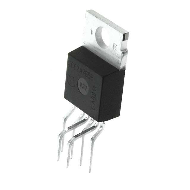
| Package Case | TO-220-6 Formed Leads | Digi-Key | |
| Power Watts | 102 W | Digi-Key | |
| Supplier Device Package | PG-TO220-6-46 | Digi-Key | |
| Supply Voltage (Typ) | 8.5V ~ 21V | Digi-Key | |
| Switching Frequency (Typ) | 100kHz | Digi-Key | |
| Topology | Flyback | Digi-Key | |
| Voltage Breakdown | 650V | Digi-Key | |
| Voltage Start Up | 15 V | Digi-Key |
When To Use
-
48 V input → 12 V @ 8 A isolated power supply: The 650 V breakdown rating and built-in internal switch make this part ideal for a flyback topology with wide input voltage swings and galvanic isolation. A synchronous buck controller would fail due to lack of isolation and risk of shoot-through on the high-side switch at 48 V.
-
Industrial sensor module with 15 V to 21 V input → 5 V @ 5 A output: The 102 W power rating and 100 kHz switching frequency support robust continuous operation within this voltage range. Using a linear regulator here would cause severe thermal runaway due to excessive dissipation at these power levels.
-
Isolated auxiliary power supply on 230 VAC flyback converter: The internal switch and fault protections (current limiting, over-temperature, open loop) simplify design for isolated output rails. A non-isolated synchronous buck would fail to provide necessary output isolation, risking system-level damage and safety violations.
When Not To Use
-
Output current demand above 8 A continuous: The 102 W power rating and internal switch limit maximum current capability. Use a multi-phase buck controller instead to share current load and reduce stress on individual switches.
-
Battery-powered device with extended standby time: The part’s quiescent current is not optimized for ultra-low power consumption. Use a low-IQ PFM buck to minimize quiescent current and extend battery life.
-
High-frequency switching above 500 kHz for compact magnetics: The fixed 100 kHz switching frequency limits size reduction of passive components. Use a high-frequency buck controller designed for >500 kHz operation to shrink magnetics and improve transient response.
Application Notes
-
The switching node (SW) pin must have a low-inductance, wide copper area for the flyback transformer’s primary switch connection to minimize voltage spikes and EMI.
-
Pins 3 and the feedback and control pin are noise sensitive; route these traces away from the SW node and high-current return paths to avoid jitter and erratic switching.
-
Place a local ceramic capacitor (<100 nF) as close as possible across the supply voltage pin and ground to stabilize the internal regulator and reduce high-frequency noise.
-
Use a grounded copper pour or guard ring around the control pin traces to prevent coupling from the high dV/dt at the SW node.
-
Avoid long leads or wiring loops on the transformer primary; these increase parasitic inductance and can cause ringing that triggers false over-voltage or over-current faults.
Gotchas
-
[Soft-start misinterpretation]: Designers may assume the internal soft-start fully protects against inrush current on startup. In reality, without a properly sized input bulk capacitor, the device can experience initial current spikes causing false over-current faults or premature shutdown.
Fix: Verify input bulk capacitance and measure startup current waveform to ensure soft-start ramp matches expected timing. -
[Fault protection interaction]: The current limiting and over-temperature protections share internal sensing nodes, but their thresholds are temperature-dependent and can shift under high junction temperatures. This can cause intermittent shutdowns under heavy load and elevated ambient conditions, which may look like unstable output voltage.
Fix: Use thermal imaging on the package during worst-case load and ensure adequate heatsinking; add margin to load current rating. -
[High ESR output capacitor effect]: Excessively high ESR on the output capacitor can destabilize the feedback loop due to altered phase margin, causing subharmonic oscillations or output voltage ripple beyond specification. These effects can be subtle and not appear in initial simulations.
Fix: Follow recommended output capacitor types and ESR ranges from the datasheet and validate loop stability on the bench with a spectrum analyzer. -
[Minimum load requirement]: The internal switch and control loop expect a minimum load to maintain stable operation. Running the converter at very light load or no load can cause output voltage overshoot or switching jitter, which may be misdiagnosed as a device fault.
Fix: Add a small bleed resistor or dummy load (typically 1–5% of full load) on the output to ensure stable regulation during light load conditions.