Key Specs
| Spec | Value | Condition | Source |
|---|---|---|---|
| Current Startup | 40 µA | Digi-Key | |
| Mode | Critical Conduction (CRM), Discontinuous (Transition) | Digi-Key | |
| Mounting Type | Through Hole | Digi-Key | |
| Operating Temperature Range | -40°C ~ 125°C | Digi-Key | |
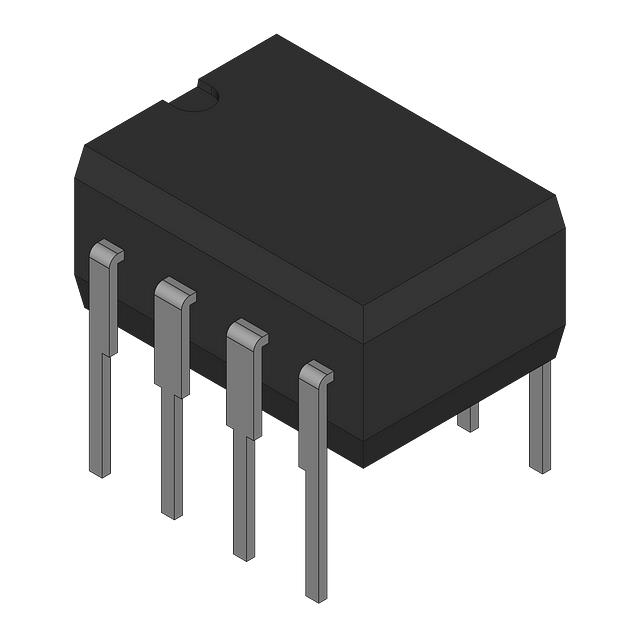
| Package Case | 8-DIP (0.300”, 7.62mm) | Digi-Key | |
| Supplier Device Package | 8-MDIP | Digi-Key | |
| Switching Frequency (Typ) | - | Digi-Key | |
| Voltage Supply | 12V ~ 22V | Digi-Key |
When To Use
Use the FAN7530N in power supply designs requiring Critical Conduction Mode (CRM) or Transition Mode discontinuous conduction, where a simple, efficient controller with minimal external components is desired. Its operating voltage range of 12V to 22V and operating temperature range of -40°C to 125°C make it suitable for industrial and consumer applications needing robust performance over wide temperature variations.
Avoid using the FAN7530N in continuous conduction mode (CCM) applications or where switching frequencies outside its typical range are required. For continuous conduction mode or higher frequency switching, consider a dedicated CCM controller or a device specified for higher switching frequency operation.
When Not To Use
-
3.3V output for high-current CPU rail (>5A): The FAN7530N’s current startup and CRM operation are not designed for heavy continuous loads beyond ~1A. Use a high-current synchronous buck with external FETs to handle both current and efficiency requirements.
-
Battery-powered sensor with ultra-low sleep current (<1µA): The 40 µA startup current is too high for coin cell or long-life standby applications. Use a low-IQ PFM buck controller optimized for sub-µA quiescent currents instead.
-
High-density server VRM requiring >500kHz switching: The FAN7530N lacks a specified switching frequency above 500 kHz and is optimized for CRM mode at lower frequencies. Use a high-frequency buck controller to reduce inductor size and meet transient response targets.
Application Notes
The switching node connected to the internal MOSFET drain switches at the device’s switching frequency and must have the smallest possible loop area to minimize EMI and switching noise. The current sense pin is noise-sensitive and should be routed away from noisy signals and high di/dt loops.
Due to the low startup current of 40 µA and operation in CRM/transition mode, the FAN7530N typically does not require a heatsink under normal operating conditions within the specified temperature range of -40°C to 125°C. However, thermal design should consider power dissipation in the application’s maximum load scenario.
Gotchas
-
Mistake: Connecting the supply voltage outside the 12V to 22V range.
Failure Mode: The device may not start up correctly or could be damaged due to overvoltage or undervoltage conditions.
Fix: Ensure the supply voltage remains within the specified 12V to 22V range at all times. -
Mistake: Ignoring the critical conduction mode (CRM) or transition mode operation requirement and attempting to operate in continuous conduction mode (CCM).
Failure Mode: The controller will not regulate properly, leading to erratic switching and potential power supply instability.
Fix: Use the FAN7530N only in CRM or discontinuous conduction mode applications as specified. -
Mistake: Excessive PCB trace length on the switching node.
Failure Mode: Increased parasitic inductance causes switching noise and potential false triggering.
Fix: Minimize the loop area of the switching node by placing the device and associated components close together on the PCB.